There are many ways to program the Arduino. If you want to use the Arduino as a PLC or PLC, you can use the "plcladdersimulator2". The name is a bit misleading, of course you can wonderfully simulate PLC / PLC controls with the software. But the created program can also be output as an Arduino code (.INO file) and uploaded to the Arduino. If you want to use your Arduino as a SPS / PLC or use a "controllino" right away, the "plcladdersimulator2" is great software. You do not need any programming knowledge but can create your program as usual in a PLC / PLC ladder editor.
Manufacturer's website: https://plcladdersimulator2.weebly.com/
APP at Google Play: https://play.google.com/store/apps/details?id=com.casdata.plcladdersimulator2
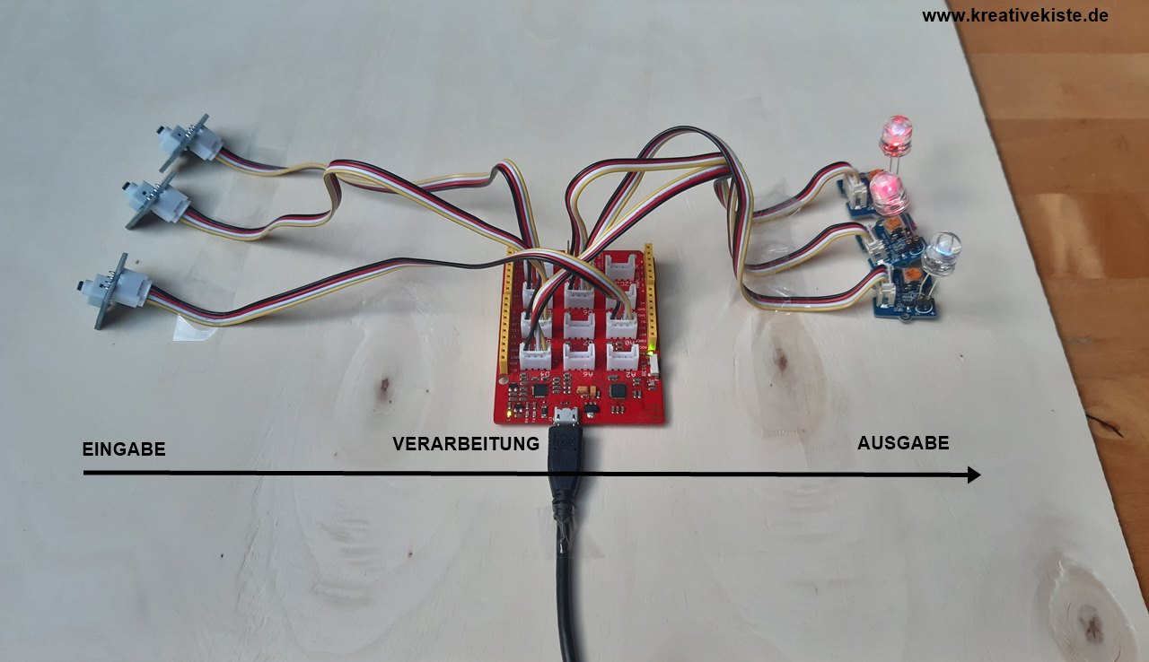
"plcladdersimulator2" is a pretty "powerful" software, the basic version with which you can work quite well for free. If you want to program an Arduino Mega or need more "lines" you have to activate the full version for a few euros. The software and the hardware, like all PLC controls and regulators, work according to the input-processing-output principle.
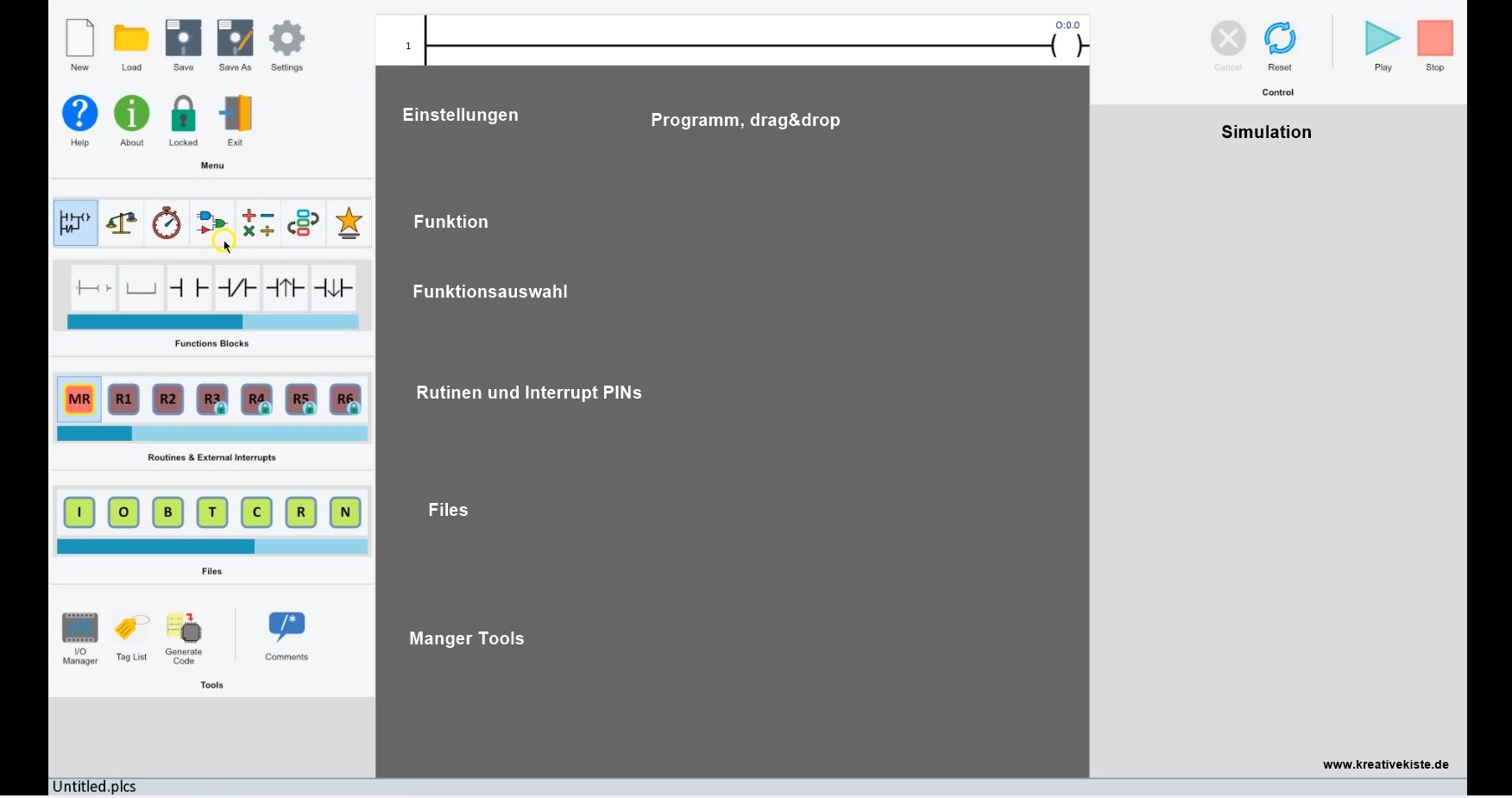
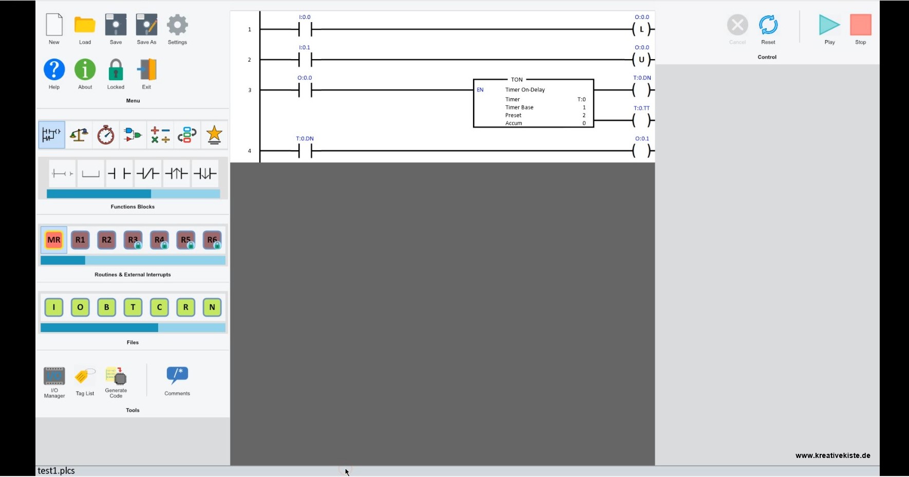
The surface of the Arduino Ladder Logic:
The surface is simple, clear, tidy and very similar to many PLC / PLC programs.
On the left are settings, functions and tools.
The program field is in the middle, the various functions are drawn in here using drag & drop.
With a left double click you can "edit" the functions
The functions can be deleted with a right double click
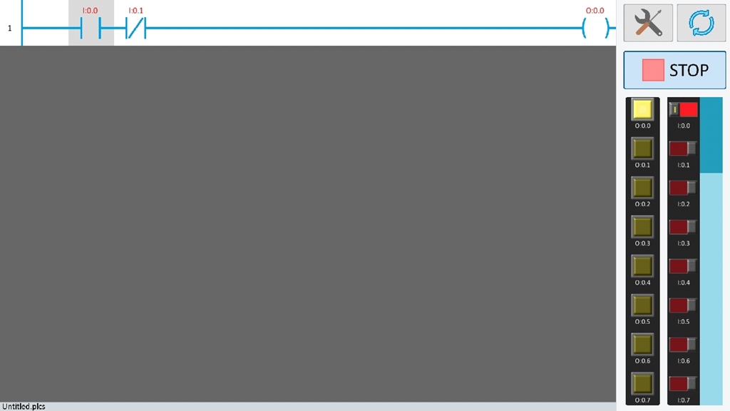
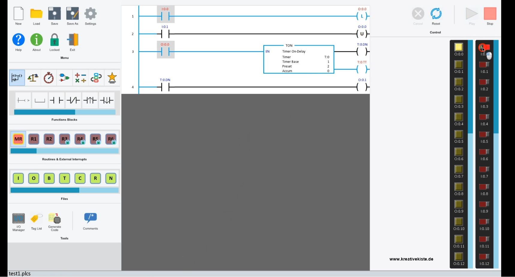
On the right you can start the simulation, switch the inputs and see which position the outputs have
New "conductors" as new contacts are inserted with 1 lines. Links under the first contact line are inserted with 2.
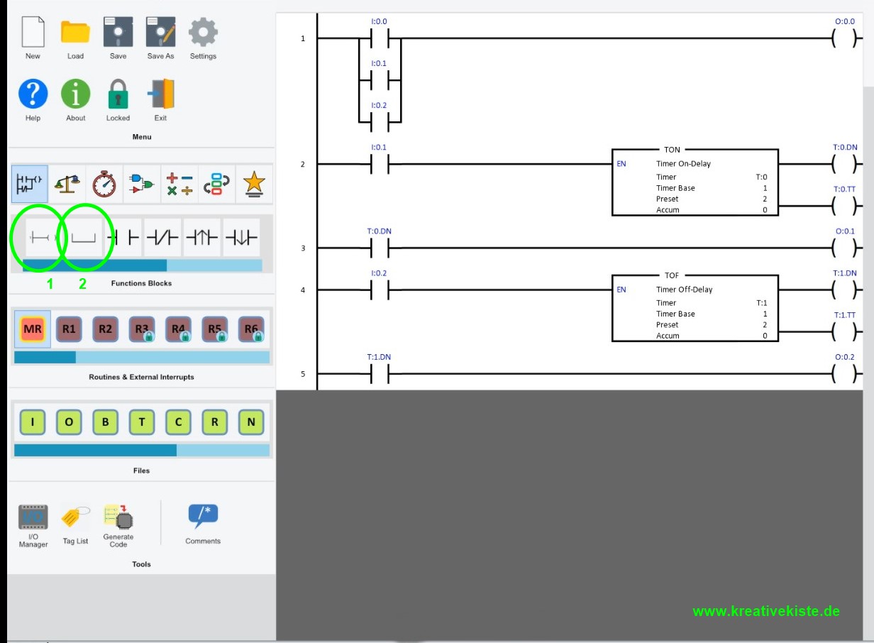
The program is located in the middle and is based (or at least remembers) the IEC standard EN 61131-3 for graphic programming according to a ladder diagram. There are all common functions such as setting and resetting, the TON (Timer On delay) and TOF (Timer Off delay) etc. The inputs are on the left, then the functions and on the right are the outputs and "flags")
As with many programs, there is also a practical simulation here, which considerably simplifies "debugging" and the understanding of the "ladder diagram" or "ladder diagram" controls and regulations.
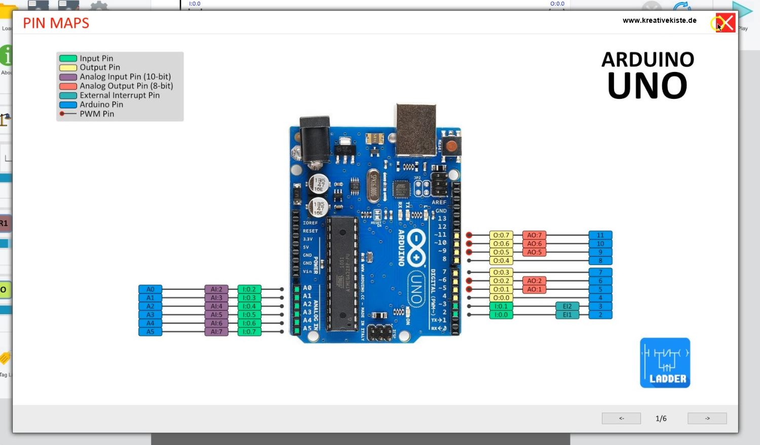
There is also a "PIN MAP", also known as "PIN OUT & PIN IN", which shows which inputs and outputs are "connected" to which contact numbers in the ladder diagram. With the Arduino UNO, the inputs are the digital PINs 1 and 2 and the analogue PINs A0 to A5, starting at 0.0 and the outputs are the digital PINs 4 to 11, also starting at 0.0 ..
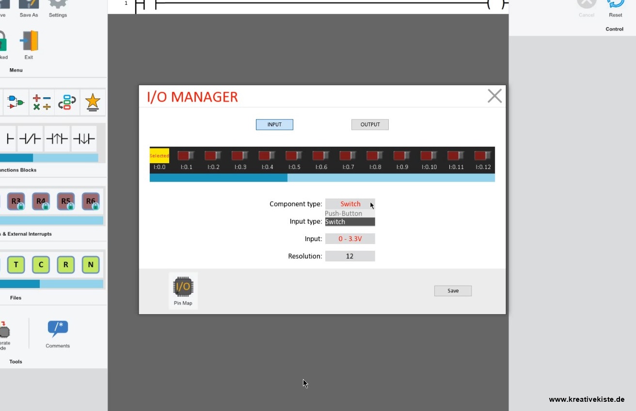
A "PIN setup" can also be carried out via the I / O manager.
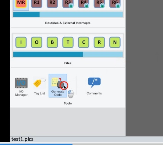
Upload the PLC program to the Arduino:
Unfortunately, the code is not loaded directly onto the Arduino. An .INO file is created using the "create code" button.
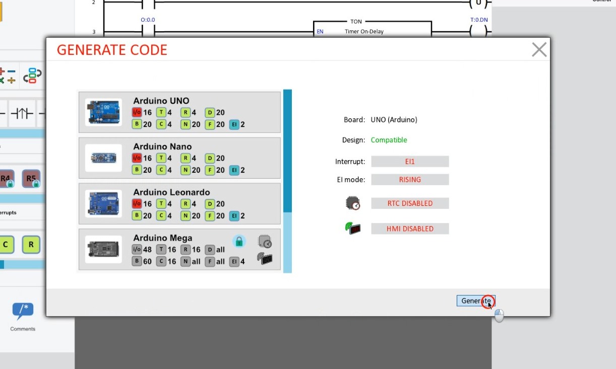
But first you can see whether this is OK as "compatible", if everything is OK, the file is generated using the "genrate" button.
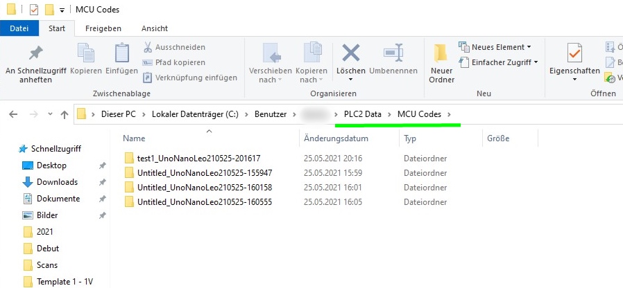
The file is then in the user folder -> PLC2 Data -> MCUCodes, open the .INO file, set the port and the appropriate board and click on upland.
The program is also available as an APP for the smartphone, great for in between or for tackling spontaneous ideas, but without a PC it remains a PLC simulation.